Running ROS 2 in Docker is a practical way to make robotics development more reproducible. Robotics projects often depend on specific Ubuntu versions, DDS settings, package combinations, and middleware behavior. Containers help reduce the classic “it works on my machine” problem.
Why ROS 2 and Docker Work Well Together
You can standardize the development environment across machines.
You can onboard collaborators faster.
You can test builds in CI using the same container image.
You can isolate dependencies for multiple robotics projects.
A Basic ROS 2 Dockerfile
FROM ros:humble
WORKDIR /ws
RUN apt-get update && apt-get install -y     python3-colcon-common-extensions     && rm -rf /var/lib/apt/lists/*
COPY . /ws
RUN . /opt/ros/humble/setup.sh && colcon build
CMD ["bash"]
This is only a starting point, but it shows the general pattern: start from a ROS base image, install required tools, copy the workspace, and build it.
Practical Challenges
Robotics containers are not always as simple as web application containers. You may also need to think about:
GUI forwarding for RViz or Gazebo,
access to USB devices and sensors,
network configuration for DDS discovery,
volume mounts for source code and logs.
A Useful Development Workflow
Keep the source code mounted into the container during development.
Use a stable base image for the ROS distribution.
Separate frequently changing code from slower-changing dependencies to speed up rebuilds.
Use Docker Compose or scripts to simplify multi-container robotics setups.
Final Thoughts
Docker is not a magic answer for robotics, but it is extremely helpful for reproducibility. When combined with ROS 2, it gives teams a cleaner and more portable development workflow, especially when projects grow beyond one machine or one engineer.
According to inventor and artist Leonardo Da Vinci ‘Learning Never Exhausts the Mind’ and over the past decade here at SoftBank Robotics we have found that to be consistently true.
NAO History
In 2004 Aldebaran Robotics (Now SoftBank Robotics) launched project NAO which over time has come to revolutionize the way humans and robots interact with each other. NAO is a 58cm tall humanoid robot that is continuously evolving to help support humans in all their endeavors.
Capabilities
NAO’s abilities range from facial recognition, learning from past conversations to automated movement. NAO has already shown his more advanced capabilities through concierging at hotels, aided researchers in over 70 different institutions.
In Education
Most recently, NAO has been put to use in multiple South Australian schools; there NAO supports teachers, challenges students and is changing the way they interact. Monica Williams, a researcher from The Association of Independent Schools of South Australia noted that “What surprised the director was the depth of the students’ understanding and that once the teachers opened up to working with the students on the robot they continually saw things that surprised all of us as to what students were capable of”. Additionally, these schools found that both boys and girls were equally captivated by NAO and even began learning how to code for NAO using Python, an industry standard. Similarly, with the help of Choreographe and multiple licenses provided for schools, students can work with a virtual NAO as they take turns working with the actual NAO which encourages each student to learn at their own pace.
NAO has also been hard at work in the special education field, supporting students in developing skills like turn taking, spontaneous communication and social interaction with NAO and others.
Through the years, NAO has proven that whether you are a teacher wanting to empower your students, a hotel in need of a concierge or a student who could use a helping hand, NAO will be there for you, with capabilities that surprise and engage people.
NAO is more than just a robot, NAO can connect with real people and has the ability to become a core part of a community. Like us, NAO will keep developing and learning and if his time in Australia shows us anything, it is that NAO’s mind is far from exhausted.
Industrial robots are built for repeatability, precision, and productivity. They are common in manufacturing because they can perform structured tasks for long periods with consistent quality.
What an Industrial Robot Usually Looks Like
Many industrial robots are multi-joint robotic arms. They use motors, gear systems, controllers, and sensors to move a tool through space. That tool may be a gripper, a welding head, a camera, or a painting nozzle.
Common Applications
Welding: repeatable movement along a fixed path.
Pick and place: moving parts from one station to another.
Painting: smooth, controlled trajectories with good coverage.
Assembly: inserting or fastening components.
Inspection: using cameras or sensors for quality control.
Why Robots Are Useful
They reduce variation in repetitive processes.
They improve throughput.
They can work in environments that are dangerous or tiring for humans.
They make process timing easier to predict.
A Practical Engineering View
Using a robot well is not only about programming motion. It also involves cell layout, safety design, cycle time analysis, tooling, calibration, and maintenance. In many factories, the real challenge is system integration, not only robot control.
Example Workflow
A conveyor brings a part into a fixed position.
A vision system checks orientation.
The robot picks the part with a gripper.
It places the part in the next station with millimeter-level repeatability.
A PLC coordinates timing with the rest of the line.
Final Thoughts
Industrial robots are one of the clearest examples of engineering value in practice. They combine mechanics, electronics, control, and software into systems that solve real production problems every day.
Robot operating system is a dedicated software system for programming and controlling robots, including tools for programming, visualizing, directly interacting with hardware, and connecting robot communities around the world. In general, if you want to program and control a robot, using ROS software will make the execution much faster and less painful. And you don’t need to sit and rewrite things that others have already done, but there are things that you want to rewrite are not capable. Like Lidar or Radar driver.
ROS runs on Ubuntu, so to use ROS first you must install Linux. For those who do not know how to install Linux and ros, I have this link for you:
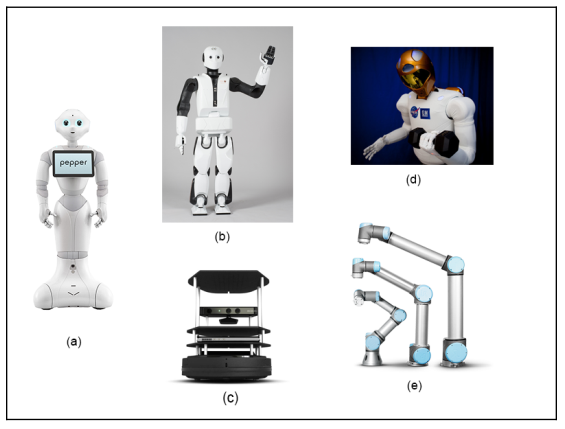
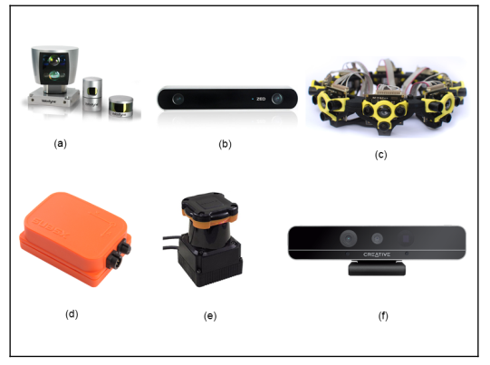
The robots and sensors supported by ROS:
The above are supported robots, starting from Pepper (a), REEM-C (b), Turtlebot (c), Robotnaut (d) and Universal robot (e). In addition, the sensors supported by ROS include LIDAR, SICK laser lms1xx, lms2xx, Hokuyo, Kinect-v2, Velodyne .., for more details, you can see the picture below.
Basic understanding of how ROS work:
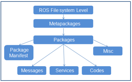
Basically ROS files are laid out and behave like this, top down in the following order, metapackages, packages, packages manifest, Misc, messages, Services, codes:
In that package (Metapackages) is a group of packages (packages) related to each other. For example, in ROS there is a total package called Navigation, this package contains all packages related to the movement of the robot, including body movement, wheels, related algorithms such as Kalman, Particle filter. … When we install the master package, it means all the sub-packages in it are also installed.
Packages (Packages), here I translate them as packages for easy understanding, the concept of packages is very important, we can say that the package is the most basic atoms that make up ROS. In one package includes, ROSnode, datasets, configuration files, source files, all bundled in one “package”. However, although there are many things in one package, but to work, we only need to care about 2 things in one package, which is the src folder, which contains our source code, and the Cmake.txt file, here is where we declare the libraries needed to execute (compile) code.
Interaction between nodes in ROS
ROS computation graph is a big picture of the interaction of nodes and topics with each other.
In the picture above, we can see that the Master is the nodes that connect all the remaining nodes.
Nodes: ROS nodes are simply the process of using the ROS API to communicate with each other. A robot may have many nodes to perform its communication. For example, a self-driving robot will have the following nodes, node that reads data from Laser scanner, Kinect camera, localization and mapping, node sends speed command to the steering wheel system.
Master: ROS master acts as an intermediate node connecting between different nodes. Master covers information about all nodes running in the ROS environment. It will swap the details of one button with the other to establish a connection between them. After exchanging information, communication will begin between the two ROS nodes. When you run a ROS program, ros_master always must run it first. You can run ros master by -> terminal-> roscore.
Message: ROS nodes can communicate with each other by sending and receiving data in the form of ROS mesage. ROS message is a data structure used by ROS nodes to exchange data. It is like a protocol, format the information sent to the nodes, such as string, float, int …
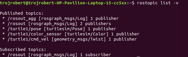
Topic: One of the methods for communicating and exchanging messages between two nodes is called ROS Topic. ROS Topic is like a message channel, in which data is exchanged by ROS message. Each topic will have a different name depending on what information it will be in charge of providing. One Node will publish information for a Topic and another node can read from the Topic by subcrible to it. Just like you want to watch your videos, you must subcrible your channel. If you want to see which topics you are running on, the command is rostopic list, if you want to see a certain topic see what nodes are publishing or subcrible on it. Then the command is rostopic info / terntopic. If you want to see if there is anything in that topic, type rostopic echo / terntopic.
Service: Service is a different type of communication method from Topic. Topic uses a publish or subcrible interaction, but in the service, it interacts in a request – response fashion. This is exactly like the network side. One node will act as a server, there is a permanent server run and when the Node client sends a service request to the server. The server will perform the service and send the result to the client. The client node must wait until the server responds with the result. The server is especially useful when we need to execute something that takes a long time to process, so we leave it on the server, when we need it we call.
Wikipedia defines Robot as a machine capable of carrying out complex series of actions automatically. The advantages and importance of Robots are contentious, the robotics field is evolving every day and the benefits of robots are becoming inevitable. This article is not meant to discuss the advantages of robots, but to get you started with ROS(Robot Operating System).
This article describes ROS installation, file system, packages, nodes, topics, messages, service, publishers, subscribers, and ROS GUI tools. The programming language used in this article is Python. Refer to this github repo for the codes in this article.
ROS is an open-source meta operating system or a middleware used in programming Robots. It consists of packages, software, building tools for distributed computing, architecture for distributed communication between machines and applications. It also provides tools and libraries for obtaining, building, writing, and running code across multiple computers. It can be programmed using python, c++, and lisp.
ROS vs Framework vs OS(Operating System)
Operating System(OS) manages communication between computer software and hardware. In the process of managing this communication, it allocates resources like the central processing unit(CPU), memory, and storage. Examples are windows, Linux, android, mac OS, etc.
Framework in computer programming is an abstraction in which software providing generic functionality can be selectively changed by additional user-written code, thus providing application-specific software. Software frameworks may include support programs, compilers, code libraries, toolsets, and application programming interfaces(APIs) that bring together all the different components to enable the development of a project or system. Examples are Django, Laravel, Tensorflow, Flutter, etc.
Robot Operating System(ROS) is not a full-fledged operating system, it is a “meta operating system”. It is built on top of a full operating system. It is called an OS because it also provides the services you would expect from an operating system, including hardware abstraction, low-level device control, implementation of commonly-used functionality, message-passing between processes, and package management. It is a series of packages that can be installed on a full operating system like Ubuntu.
ROS level of concepts
Filesystem level — these are resources located on the disk. For example, packages, package manifests (package.xml), repositories, messages types, service types, etc.
Computation level — these involve the communications between peer to peer networks of ROS. Examples are nodes, master, parameter server, messages, topics, services, bags.
Community level — these involve the exchange of software and knowledge between members of the community. Examples are distributions, repositories, ROS wiki.
catkin is the new build system (generate executable files from source files) for ROS while rosbuild was the build system used in the past. catkin uses CMake more cleanly and only enhances CMake where it falls short on features, while rosbuild uses CMake but invokes it from Makefiles and builds each package separately and in-source. catkin was designed to be more conventional than rosbuild, allowing for better distribution of packages, better cross-compiling support, and better portability.
ROS Distributions, Installation, and File System
ROS distributions are named alphabetically. For instance, the last 3 distributions are Lunar Loggerhead, Melodic Morenia, and Noetic Ninjemys. ROS can be officially built on Linux distributions but it also supports other operating systems. This article uses ROS Melodic distribution on Ubuntu 18 Linux distribution.
You can install other distributions by changing the distribution name. For instance, you can change melodic to noetic but note noetic support Ubuntu Focal Fossa(20.04). This installation installs the full version, you can install smaller versions for instance:
This installation does not contain the GUI tools.
After proper installation, you need to source the ROS setup script. source command reads and executes commands from the file specified as its argument in the current shell environment.
To avoid sourcing the setup file every time a new terminal is opened, you can add the command to the .bashrc file. It will automatically run when you open a new terminal.
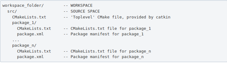
ROS packages are saved in a catkin “workspace” folder. The package folders are saved in the “src” folder in the catkin “workspace”.
The catkin_make command builds all packages located in “catkin_ws/src” folder. After running catkin_make command, two new folders “build” and “devel” will be created. Note, you should always run catkin_make command when you are in the “catkin_ws” directory. The “build” folder is where CMake and Make are invoked, while the “devel” folder contains any generated files and targets, including setup.sh files. A “CMackeLists.txt” file is also created in the src folder(I explained more about this file below).
Ros Package — contains libraries, executables, scripts, and other artifacts for a specific ROS program. Packages are used for structuring specific programs. Files in a package also have a specific structure. A ROS package folder could contain:
launch folder — it contains the launch files(launch files are used to run multiple nodes).
src folder — it contains the source files for instance python or c++ files.
package.xml — also called manifest file, contains package metadata, dependencies, and other metadata related to the package.
CMakeLists.txt -it contains executables, libraries, etc. it is catkin metapackage.
A ROS package must be in the parent “catkin_ws/src” folder, its folder, and must contain package.xml and CmakeList.txt.
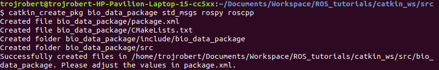
Creating a ros package
This command creates a package called “bio_data_package” with dependencies std_msgs, rospy, and roscpp. This command automatically creates a folder named the package name, this package folder contains the “package.xml”, “CMakeLists.txt”, “include” folder and “src” folder. The “src” folder in the workspace folder is different from the “src” folder created in the package folder. Build all the packages in “catkin/src” by running catkin_make, source the “setup.bash” in the “devel” folder to add new environment variables.
ROS Package command-line tool — rospack
rospack is used to get information about packages. Note: Tab completion, press the tab key once to complete a command, and twice to show you suggestions. For instance, you press tab twice after rospack.
rospack list — list all the ROS packages in your workspace rospack find bio_data_package — to output the path of package “bio_data_package”
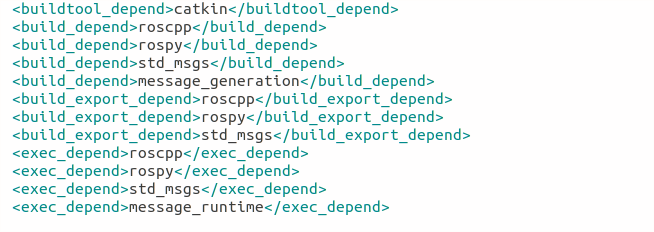
The package.xml contains tags that describe the package. The required tags are name, version, description, maintainer and license.
<name> – the name of the package.
<version> – the version of the package, usually it should be three integers separated by dots.
<description> – a description of the package.
<maintainer> – information about the maintainer i.e someone you can contact if you need more information about the package.
<license> – the license to the package.
<buildtool_depend>(build tool dependency) – the build system required to build the package, this is usually catkin or rosbuild.
<build_depend>(build dependency) – the dependencies of the package, each dependency is enclosed in a build_depend tag.
<build_export_depend>(build export dependency) – a dependency that is included in the headers in public headers in the package.
<exec_depend>(Execution Dependency) – a dependency that is among the shared libraries.
<test_depend>(Test Dependency) – a dependency required for unit test.
<doc depend>(Documentation Tool Dependency) – a dependency required to generate documentation.
A ROS node is an executable that uses ROS to communicate with other nodes. The concept of ros node helps in fault tolerance as each node does not depend on another node.
ROS Master — provides naming and registration services to the rest of the nodes in the ROS system. Publishers and Subscribers register to the master, then ROS Master tracks ROS topics being published by the publisher and ROS Topics being subscribed to by the subscribers. It also provides the Parameter Server.
rosout — rosout is the name of the console log reporting mechanism in ROS. rosout subscribes to /rosout topic.
Parameter Server — is a shared, multi-variate dictionary that is accessible via network APIs. Nodes use this server to store and retrieve parameters at runtime.
roscore — master + rosout + parameter server. It controls the entire ROS system. It must be running to enable ROS nodes to communicate. It is a collection of nodes and programs that are pre-requisites of a ROS-based system.
Once roscore is running, you can open a new terminal to run other ros nodes.
ROS node command-line tool — rosnode
ROS Run
rosrun — this is used to run a node in a package
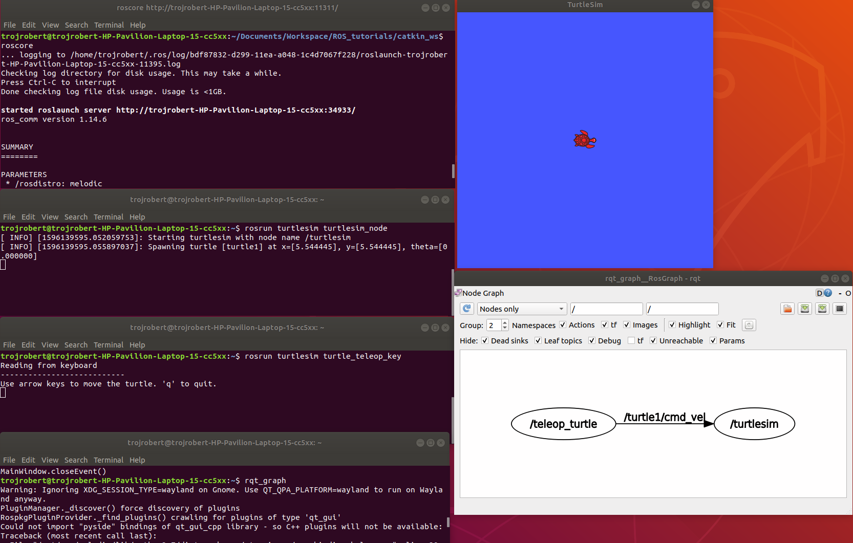
turtlesim_node display a GUI with a turtle.
Run the command on a different terminal
The turtle_teleop_key node provides a way to control the turtle with a keyboard. Click on the terminal where you ran rosrun turtlesim turtle_teleop_key, then press the arrow keys, the turtle moves in the direction of the arrow key pressed.
Ros Topics are the buses used by ROS nodes to exchange messages. Imagine a ROS Topic as a water pipe and ROS Message as the water, the two ends of the pipe are where the nodes are located. Topic transport message between a publisher node and a subscriber node. Ros Topics have anonymous publish/subscribe semantics. Nodes that generate message/ data publish to a specific topic, and nodes that consume or need data subscribed to a specific topic. The relationship between publishers and subscribers is many to many.
In the example above, the turtle_teleop_key node publishes the key pressed to the /turtle/cmd_vel topic and the turtlesim node subscribes to that same topic.
ROS topic command-line tool — rostopic
rostopic hz [topic] (shows how fast the messages are publishing) rostopic hz /turtle/cmd_vel
Nodes communicate by sending ROS messages to each other using ROS Topic. A message can be of primitive type integer, floating-point, boolean, etc. A publisher and subscriber should communicate using the same topic type. The topic type is determined by the message type.
Creating a ROS message
Create a msg folder in your package folder. We created a new package call bio_data_package in the example above. Inside this newly created “msg” folder, create a msg file called name.msg
Step 1
Copy the following command into the “name.msg” file. You can also check on github
Now you should have something like this, please don’t modify other lines.
Step 3
Open the CmakeList.txt file for the bio_data_package package in a text editor. This is needed for steps 3 to 6. Check a sample file on github
Modify the find_package call by adding message generation to its components. Now you should have something similar to this.
Step 4
Modify the catkin_package by adding message_runtine
Step 5
Modify add_message_files by adding the name.msg, this enable CMake to reconfigure the project with the new msg file.
Step 6
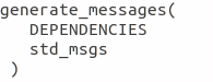
Modify generate_message by removing the # symbols to uncomment it.
Step 7
ROS message command-line tool — rosmsg
Show the description of the new message created
ROS service is one to one two way transport, it is suitable for request/reply interactions. A ROS node(server) offers a service, while another ROS node(client) requests for the service. The server sends a response back to the client. Services are defined using srv files. srv files are just like msg files, except they contain two parts: a request and a response. Services also have types like topics.
Creating a ROS Service
Create a srv folder in your package folder. You created a new package call bio_data_package in the example above. Inside this newly created “srv” folder, create a srv file called full_name.srv. A srv file is used to describe a service, srv files are stored in the “srv” folder.
Copy the following command into the “full_name.srv” file. A sample is on github
A srv file has two parts separated by -, the first part is the request while the second part is the response.
Do the steps required in creating a ROS message, but instead of Step 5, do thhe following. Please don’t repeat all the steps if you have done them before.
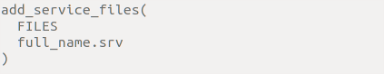
Step 5(specific for ROS service)
Modify add_service_files by adding the “full_name.srv”, this enables CMake to reconfigure the project with the new srv file.
ROS service command-line tool — rossrv
Show the description of the new service created
ROS Services vs ROS Topic
Involves the communication between any two nodes
Involves the communication between Publishers and Subscribers
It is a two way transport
It is a one way transport
It is one to one
It is many to many
Involves a request/ reply pattern
Does not involves a Request/reply pattern
ROS Publisher and Subscriber
Publisher and subscriber is many to many but one way transport. A node sends out a message by publishing it to a given topic. The topic is a name that is used to identify the content of the message. A node that is interested in a certain kind of data will subscribe to the appropriate topic.
Creating a Publisher
A publisher is a node that publishes messages into a topic. Create a scripts folder in your package folder, we created a new package call bio_data_package in the example above, inside this newly created “script” created folder, create a python file called writer_pub.py
Copy the following code into the “writer_pub.py” file. Sample is on github
Creating a Subscriber
A subscriber is a node that gets messages from a topic. Create a python file called reader_sub.py in the “scripts” folder.
Copy the following code into the “reader_sub.py” file. A sample is on github
Modify the caktin_install_python() call in CMameLists.txt
roswtf is a tool for diagnosing issues with a running ROS file system. It evaluates ROS setup like environment variables, packages , stacks, launch files and configuration issues.
rqt_console is a tool that displays messages being published to rosout. These messages have different level of severity like debug, info, warn, error, fatal.
Terminal 2rosrun turtlesim turtlesim_node
Terminal 3rosrun turtlesim turtle
Now move the turtle to the wall
rqt _graph
This shows nodes and the topics the nodes are communicating on.
rqt _plot
Display the scrolling time plot of data published on a topic
rqt
rqt contain most ROS GUI tools, you can select the on you want in the Plugib tab.
Other ROS concepts
ROS Launch — is used for starting and stopping multiple ros nodes. It is used to execute a ros program which is a .launch file.
ROS Stack — this contain several packages.
rosbag — published topics are saved as .bag file, rosbag command line tool is used to work with bag files.
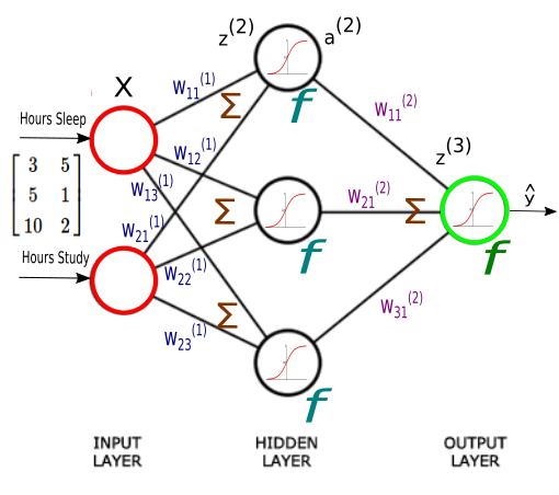
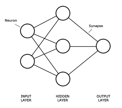
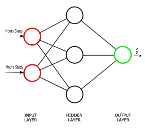
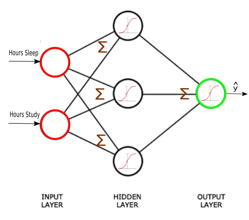
The Neural network structure is: one, input layer, one output layer, and layers between are hidden layer.
Introduction
An Artificial Neural Network (ANN) is an interconnected group of nodes, similar to the our brain network.
Here, we have three layers, and each circular node represents a neuron and a line represents a connection from the output of one neuron to the input of another.
The first layer has input neurons which send data via synapses to the second layer of neurons, and then via more synapses to the third layer of output neurons.
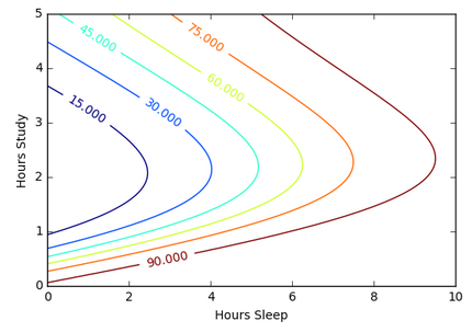
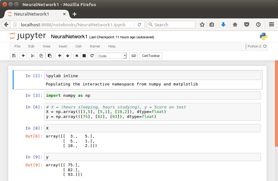
Suppose we want to predict our test score based on how many hours we sleep and how many hours we study the night before.
In other words, we want to predict output value yy which are scores for a given set of input values XX which are hours of (sleep, study).
XX (sleep, study)
y (test score)
(3,5)
75
(5,1)
82
(10,2)
93
(8,3)
?
In our machine learning approach, we’ll use the python to store our data in 2-dimensional numpy arrays.
We’ll use the data to train a model to predict how we will do on our next test.
This is a supervised regression problem.
It’s supervised because our examples have outputs(yy).
It’s a regression because we’re predicting the test score, which is a continuous output.
If we we’re predicting the grade (A,B, etc.), however, this is going to be a classification problem but not a regression problem.
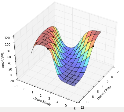
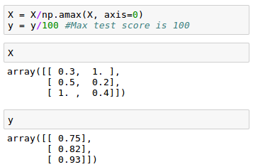
We may want to scale our data so that the result should be in [0,1].
Now we can start building our Neural Network.
We know our network must have 2 inputs(XX) and 1 output(yy).
We’ll call our output y^y^, because it’s an estimate of yy.
Any layer between our input and output layer is called a hidden layer. Here, we’re going to use just one hidden layer with 3 neurons.
Neurons synapses
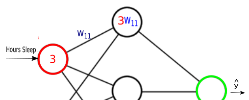
As explained in the earlier section, circles represent neurons and lines represent synapses.
Synapses have a really simple job.
They take a value from their input, multiply it by a specific weight, and output the result. In other words, the synapses store parameters called “weights” which are used to manipulate the data.
Neurons are a little more complicated.
Neurons’ job is to add together the outputs of all their synapses, and then apply an activation function.
Certain activation functions allow neural nets to model complex non-linear patterns.
For our neural network, we’re going to use sigmoid activation functions.
LiDAR stands for Light Detection and Ranging. It measures distance by sending out laser pulses and calculating how long the reflected light takes to return. This makes LiDAR a powerful sensor for building 3D representations of the environment.
How LiDAR Works
The basic principle is simple: emit light, measure return time, and convert that into distance. By repeating this process rapidly across many directions, LiDAR builds a cloud of points that describe the surrounding scene.
A simplified idea looks like this:
distance = speed_of_light * time_of_flight / 2
The division by two is necessary because the pulse travels to the object and back.
Why Engineers Like LiDAR
It provides accurate geometric measurements.
It works well for mapping and obstacle detection.
It can provide dense 3D structure that cameras do not directly measure.
Common Use Cases
Autonomous driving: detect vehicles, road edges, and free space.
Mobile robotics: SLAM, obstacle avoidance, and localization.
Surveying: terrain and structural measurement.
Industrial automation: safety zones and dimensional inspection.
2D vs 3D LiDAR
2D LiDAR scans a plane and is common in indoor mobile robots. 3D LiDAR scans many vertical angles and can capture richer scene structure, which is especially useful in outdoor robotics and autonomous vehicles.
Limitations in Practice
LiDAR hardware can be expensive.
Rain, dust, and reflective surfaces may affect measurements.
Point clouds need additional processing before they become actionable information.
A strong perception pipeline is still required to interpret raw geometry.
A Practical Example
A self-driving car may use LiDAR to estimate obstacle position and shape around the vehicle. The perception stack clusters the point cloud, tracks nearby objects, and passes those results to prediction and planning modules. In a warehouse robot, a simpler LiDAR may be enough for 2D obstacle detection and map building.
Why Fusion Still Matters
LiDAR is powerful, but no sensor should be treated as perfect. Cameras provide color and semantic detail. Radar works well in adverse weather. IMU and odometry help stabilize motion estimates. Sensor fusion is therefore the practical engineering answer in most real systems.
Final Thoughts
LiDAR is one of the most important sensing technologies in robotics and autonomy because it turns distance measurement into a usable geometric view of the world. Its value is not just in the hardware, but in how well it is integrated into the full system.
ROS, or the Robot Operating System, is not an operating system in the traditional sense. It is a software framework and ecosystem that helps engineers build modular robot applications. ROS became popular because robotics systems are naturally complex, and ROS provides a common structure for connecting sensors, algorithms, visualization tools, and control logic.
Why ROS Exists
A real robot is made of many components: camera drivers, motor controllers, localization, mapping, planning, perception, logging, simulation, and more. Building all of that from scratch in a tightly coupled application quickly becomes unmanageable. ROS encourages a distributed architecture where components communicate through well-defined interfaces.
Core Concepts
Nodes
A node is a running process that performs one specific task. For example, one node may read LiDAR data, another may estimate odometry, and another may visualize the robot state.
Topics
Topics support asynchronous publish/subscribe communication. A LiDAR node may publish scan data, and multiple subscribers may consume it at the same time.
Services
Services are request/response interactions. They are useful for operations such as resetting a subsystem or requesting a map snapshot.
Actions
Actions are useful for longer-running tasks that need progress feedback, such as navigation to a goal.
TF
TF manages coordinate transforms between frames such as map, odom, base_link, and camera frames. Without TF, multi-sensor robot systems become extremely difficult to reason about.
A Simple Example
Imagine a mobile robot using ROS:
A camera node publishes images.
A LiDAR node publishes laser scans.
An odometry node estimates motion.
A SLAM node subscribes to scans and odometry to build a map.
A planner uses the map and goal position to generate a path.
A controller node sends wheel commands.
Each part can be inspected, restarted, replaced, or improved independently. That modularity is one of ROS's biggest strengths.
Tools Engineers Use Often
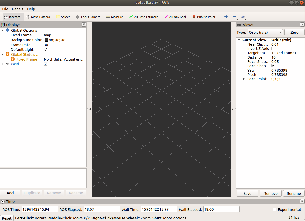
RViz for visualization
rosbag for recording and replaying data
rqt tools for debugging graphs and parameters
Gazebo or other simulators for testing
ROS 1 vs ROS 2
ROS 2 improves communication, security, real-time support, and multi-machine deployment by building on DDS. For new commercial or production-oriented systems, ROS 2 is often the better long-term choice, though ROS 1 remains important historically and in many research environments.
Final Thoughts
ROS matters because it reduces integration cost. It does not solve robotics for you, but it gives you a language and structure for connecting the parts. That is why it remains one of the most influential frameworks in modern robotics.
RTAB-Map is a widely used SLAM framework in robotics. Its name stands for Real-Time Appearance-Based Mapping, and it is designed to help robots build a map, estimate their own position, and recognize places they have seen before. One of the most interesting situations where RTAB-Map becomes especially useful is the kidnapped robot problem.
What Is the Kidnapped Robot Problem?
The kidnapped robot problem describes a situation where a robot is suddenly moved to an unknown location without knowing it. Imagine a robot navigating in a hallway. If someone picks it up, carries it to another room, and puts it down again, its internal state may still assume it is near the hallway. From the robot's point of view, its belief about position is now wrong.
This problem is important because real robots often face sensor failure, wheel slip, bad odometry, or abrupt environmental changes. A localization system must therefore do more than track motion smoothly. It also needs a way to recover when its estimate becomes inconsistent with reality.
How RTAB-Map Helps
RTAB-Map combines visual features, odometry, graph-based optimization, and loop closure detection. Instead of relying only on dead reckoning, it stores visual memories of places and compares the current scene with previously observed locations.
When the robot re-enters a known area, RTAB-Map can detect that match and add a loop closure constraint to its graph. That reduces accumulated drift and helps correct the pose estimate.
Main Components
Sensors: RGB-D cameras, stereo cameras, LiDAR, or other depth-capable sources.
Odometry: short-term motion estimate from wheel encoders, IMU, or visual odometry.
Memory management: keeps recent and useful observations while controlling computational cost.
Graph optimization: refines the map and trajectory after new constraints are added.
A Practical Example
Suppose a mobile robot is mapping an office:
It starts in corridor A and builds a map while moving.
Odometry gradually accumulates small errors.
The robot is lifted and moved to meeting room B.
Its pose estimate is now wrong because odometry alone cannot explain the jump.
Once the robot observes familiar visual landmarks or geometric structure, RTAB-Map can relocalize it against the existing map.
The graph is updated, and navigation can continue from a corrected pose.
Why Loop Closure Matters
Without loop closure, the robot's trajectory drifts over time. In a large environment that drift becomes severe enough to make the map inconsistent. Doors that should align may appear separated, and the robot may fail to navigate reliably. Loop closure is one of the key reasons modern SLAM systems remain usable over longer runs.
Deployment Considerations
Good feature-rich environments improve relocalization.
Highly repetitive corridors can make place recognition more difficult.
Sensor calibration is critical.
Large maps require careful tuning of memory and graph optimization settings.
Combining LiDAR, vision, and IMU often improves robustness.
ROS Integration
RTAB-Map integrates well with ROS and ROS 2. In practice, a common setup includes camera topics, odometry input, TF transforms, and map publishing for navigation. Engineers often use it with packages such as rtabmap_ros, RViz, and navigation stacks for local/global planning.
Final Thoughts
The kidnapped robot problem is a useful way to understand why localization cannot depend only on odometry. RTAB-Map offers a practical answer by combining memory, place recognition, and graph optimization. That makes it one of the most valuable tools for engineers working on real robot navigation systems.
RoboCup is an annual international robotic competition proposed in 1997 and founded in 1997. The aim is to promote robotics and AI research, by offering a publicly appealing, but formidable challenge. The name RoboCup is a contraction of the competition’s full name, “Robot Soccer World Cup”, but there are many other stages of the competition such as “RoboCupRescue”, “RoboCup@Home” and “RoboCupJunior”. In 2015 the world’s competition was held in Heifei, China. RoboCup 2016 will be held in Leipzig, Germany. The official goal of the project:
“By the middle of the 21st century, a team of fully autonomous humanoid robot soccer players shall win a soccer game, complying with the official rules of FIFA, against the winner of the most recent World Cup”.
As a Master student of Frankfurt University, I aslo have a project with the Robot who is the best choice for for the Robot Cup as the moment, his name is NAO.
Nao (pronounced now) is an autonomous, programmable humanoid robot developed by Aldebaran Robotics, a French robotics company headquartered in Paris. The robot’s development began with the launch of Project Nao in 2004. On 15 August 2007, Nao replaced Sony’s robot dog Aibo as the robot used in the Robot Cup Standard Platform League, an international robot soccer competition. The Nao was used in RoboCup 2008 and 2009, and the NaoV3R was chosen as the platform for the SPL at RoboCup 2010. Nao robots have been used for research and education purposes in numerous academic institutions worldwide. As of 2015, over 5,000 Nao units are in use in more than 50 countries.