Which of the following features could be useful in the identification of lane lines on the road?
Answer : Color, shape, orientation, Position of the image.
Coding up a Color Selection
Let’s code up a simple color selection in Python.
No need to download or install anything, you can just follow along in the browser for now.
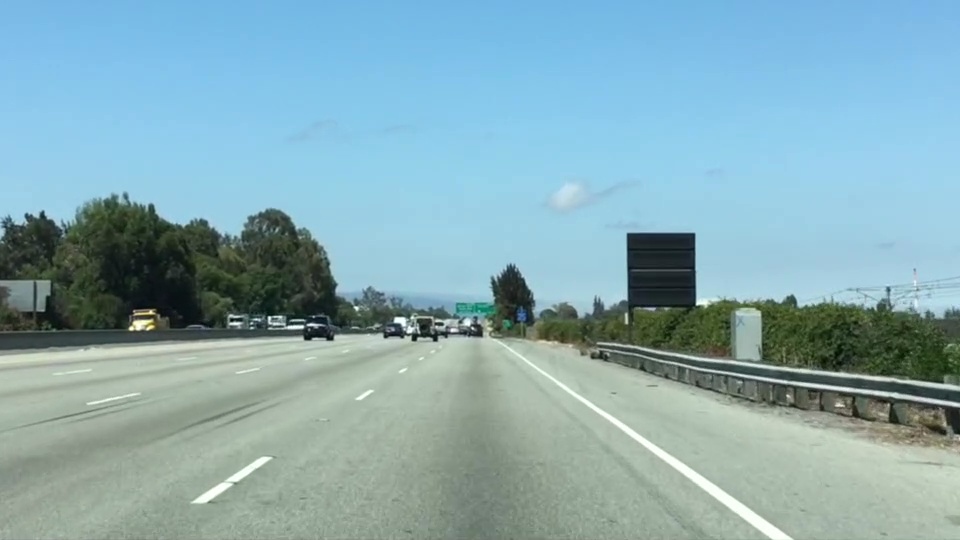
We’ll be working with the same image you saw previously.
Check out the code below. First, I import pyplot and image from matplotlib. I also import numpy for operating on the image.
import matplotlib.pyplot as plt
import matplotlib.image as mpimg
import numpy as np
I then read in an image and print out some stats. I’ll grab the x and y sizes and make a copy of the image to work with. NOTE: Always make a copy of arrays or other variables in Python. If instead, you say “a = b” then all changes you make to “a” will be reflected in “b” as well!
# Read in the image and print out some stats
image = mpimg.imread('test.jpg')
print('This image is: ',type(image),
         'with dimensions:', image.shape)

# Grab the x and y size and make a copy of the image
ysize = image.shape[0]
xsize = image.shape[1]
# Note: always make a copy rather than simply using "="
color_select = np.copy(image)
Next I define a color threshold in the variables red_threshold, green_threshold, and blue_threshold and populate rgb_threshold with these values. This vector contains the minimum values for red, green, and blue (R,G,B) that I will allow in my selection.
# Define our color selection criteria
# Note: if you run this code, you'll find these are not sensible values!!
# But you'll get a chance to play with them soon in a quiz
red_threshold = 0
green_threshold = 0
blue_threshold = 0
rgb_threshold = [red_threshold, green_threshold, blue_threshold]
Next, I’ll select any pixels below the threshold and set them to zero.
After that, all pixels that meet my color criterion (those above the threshold) will be retained, and those that do not (below the threshold) will be blacked out.
The result, color_select, is an image in which pixels that were above the threshold have been retained, and pixels below the threshold have been blacked out.
In the code snippet above, red_threshold, green_threshold and blue_threshold are all set to 0, which implies all pixels will be included in the selection.
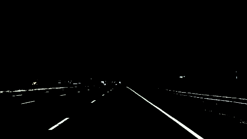
In the next quiz, you will modify the values of red_threshold, green_threshold and blue_threshold until you retain as much of the lane lines as possible while dropping everything else. Your output image should look like the one below.
No need to download or install anything, you can just follow along in the browser for now.
We’ll be working with the image below:
Check out the code below. First, I import pyplot and image from matplotlib. I also import numpy for operating on the image.
import matplotlib.pyplot as plt
import matplotlib.image as mpimg
import numpy as np
I then read in an image and print out some stats. I’ll grab the x and y sizes and make a copy of the image to work with. NOTE: Always make a copy of arrays or other variables in Python. If instead, you say “a = b” then all changes you make to “a” will be reflected in “b” as well!
# Read in the image and print out some stats
image = mpimg.imread('test.jpg')
print('This image is: ',type(image),
         'with dimensions:', image.shape)

# Grab the x and y size and make a copy of the image
ysize = image.shape[0]
xsize = image.shape[1]
# Note: always make a copy rather than simply using "="
color_select = np.copy(image)
Next I define a color threshold in the variables red_threshold, green_threshold, and blue_threshold and populate rgb_threshold with these values. This vector contains the minimum values for red, green, and blue (R,G,B) that I will allow in my selection.
# Define our color selection criteria
# Note: if you run this code, you'll find these are not sensible values!!
# But you'll get a chance to play with them soon in a quiz
red_threshold = 0
green_threshold = 0
blue_threshold = 0
rgb_threshold = [red_threshold, green_threshold, blue_threshold]
Next, I’ll select any pixels below the threshold and set them to zero.
After that, all pixels that meet my color criterion (those above the threshold) will be retained, and those that do not (below the threshold) will be blacked out.
The result, color_select, is an image in which pixels that were above the threshold have been retained, and pixels below the threshold have been blacked out.
In the code snippet above, red_threshold, green_threshold and blue_threshold are all set to 0, which implies all pixels will be included in the selection.
In the next quiz, you will modify the values of red_threshold, green_threshold and blue_threshold until you retain as much of the lane lines as possible while dropping everything else. Your output image should look like the one below.
Computer vision (CV) is a process (and a branch of computer science) that involves capturing, processing and analyzing real-world images and video to allow machines to extract meaningful, contextual information from the physical world. Today, computer vision is the foundation and a key means of testing and exploiting deep-learning models that are propelling the evolution of artificial intelligence toward ubiquitous, useful and practical applications. A lot of advancements are expected to occur between 2018 and 2020.
Back in 1955, researchers assumed they could describe the processes that make up human intelligence and automate them, creating an artificial intelligence (AI). Despite being in a time before 1st demonstration of integrated circuits (IC) in 1958, or 1st commercially available microprocessor by Intel in 1971, or the term graphic processing units (GPU) popularized by Nvidia in 1999, serious researches began and one of the most notable “AI” researches started along three distinct lines: replicating the eye (to see); replicating the visual cortex (to describe); and replicating the rest of the brain (to understand). Along these three distinct lines, various degrees of progresses have been made:
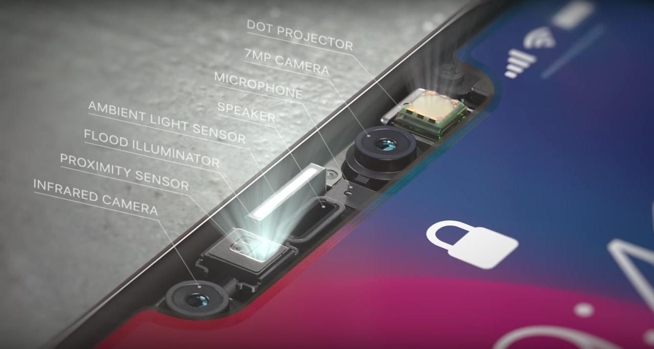
To See: Reinventing the eye is the area with most success. Over the past few decades, sensors and image processors have been created to match or even exceed the human eye’s capabilities. With larger, more optically perfect lenses and nanometer-scaled image sensor and processor, the precision and sensitivity of modern cameras are incredible, especially compared to common human eyes. Cameras can also record thousands of images per second, detect distances and see better in dark environment. However, despite the high fidelity of the outputs, they merely record the distribution of photons coming in a given direction. The best camera sensor ever made couldn’t capture images in 3D until recent hardware breakthroughs (such as flood illuminator with NIR). Modern cameras also provide a much richer and more flexible platform for hardware to work with software.
To Describe: Seeing isn’t enough, but to describe is unfathomably complex. A computer can apply a series of transformations to an image, and therefore discover edges, the objects that these edges imply, and the perspective and movement when presented with multiple pictures, and so on. The processes involve a great deal of math and statistics, and wasn’t made possible until recent advances in parallel computing powered by GPU.
To Understand: Even achieving a toddler’s intelligence has been proven to be extremely complex. Researcher could build a system that recognizes every variety of apples, from every angle, in any situation, at rest or in motion, with bites taken out, anything — and it still wouldn’t be able to recognize an orange. For that matter, it couldn’t even tell you what an apple is, whether it’s edible, how big it is or what they’re used for. Why? Because we barely understand how our minds work: Short and long term memory, input from our other senses, attention and cognition, a billion lessons learned from a trillion interactions with the world, etc. This is not a dead end, but it’s definitely hard to pin down. The past efforts of building a know-it-all expert systems have been proven to be fruitless. A new AI architecture has emerged in the past 5 years or so.
As three key interlocking factors has begun to come together since 2012, the concepts of “context, attention, intention” are slowly evolving into computer vision, a new branch of AI:
Radical New Hardware: Achieved by highly parallel GPU with the rise of foundry-fabless business model (such as TSMC and Nvidia). Liberating IC design and manufacturing from the proprietary-minded IDMs has installed more flexibility into hardware and thus allows software development to prosper. TSMC achieving 28nm mass production in 2012 has been the inflection point. Intel’s 10nm meltdown could further cement this trend.
Much More Powerful Algorithms: Unbinding software development from hardware manufacturing has invited software developers to join the revolution. With then pure software company like Microsoft bursting onto the scene in 1975, programmers have since invented many powerful tools to utilize radical new hardware, and one of the prime examples is deep neural networks (DNNs). We consider today’s DNNs to be smart because they can identify novel patterns in their input streams. Patterns their programmers did not anticipate. DNN performance on image recognition tests (ImageNet) exhibits lower error rates than humans performing the same tests.
Huge Swatches of Data: During the transition from centralized to decentralized architecture, internet was invented. With internet, collecting and integrating large amount of data becomes possible. From the internet, feeding DNNs with big data on powerful GPUs becomes a reality. With more application processors (AP) in personal devices adopting AI-enabled CV, CV applications are expanding along with more available frameworks and tools.
Let’s take a look at some of the currently notable/predictable CV applications on personal devices:
AI-driven capabilities enabled by CV have quickly become critical differentiation factors in the saturated smartphone market. These features attempt to transform smartphones from a passive utility tool to a more proactive personal assistant.
The emergence of CV in smartphones is driven by continued investments in AI techniques by major OEMs (Apple, Samsung, Huawei, and Google) and smartphone software, as well as the evolution of image sensors (Sony), image processing units (Sony and in-house ASICs) and modules’ miniaturization (Largan, etc.). For the past couple of years, new smartphones has been characterized by continued sophistication in cameras, with higher resolutions to capture more data to improve overall accuracy of visual recognition applications and integration of 3D depth-sensing technology to enhance the reliability of facial recognition. Google started it with its Tango-enabled phones, Lenovo Phab 2 and ASUS ZenFone AR, but failed to elaborate. Last year (2017), Apple introduced 3D sensing in the iPhone X, donned “TrueDepth” as part of the front-facing camera setup. Apple’s move has led to a rush in 3D sensing adoption. 3D-sensing technology is still far from mainstream, but increased availability and affordability of 3D sensors for phones is expected to continue and make it into more Android smartphones between 2018 and 2019.
If CV in smartphone follows mobile payment’s (by NFC) footstep, all premium smartphones would likely include CV capability by 2020 and 30% to 50% of non-premium smartphones would have the function before 2022. Facial or gesture recognition could become one of the standard authentication mechanisms and other CV apps would emerge as people get used to it. Here’s some directions for CV applications:
Optimize Camera Settings: Huawei uses the AI function on its Kirin 970 chip to recognize objects and scenarios to optimize the camera settings automatically. The AI-enabled camera can recognize more than 500 scenarios across 19 categories (food, group, sunset, greenery and night shot, etc.) and will adjust camera-setting features such as exposure, International Organization for Standardization (ISO) and color saturation or contrast, in real time. This enables users to get the best shot for each category. It is also able to perform object recognition linked to shopping applications and text translation based on an application developed with Microsoft Translator.
Augmented Reality (AR): Apple is already using the TrueDepth system in the iPhone X to produce Animoji, its animated emoji feature, for social networking. In the future, Apple will likely expand on AR applications. Apple acquired computer vision startup Ragaind, whose CV API can analyze photos and recognize in pictures faces, their gender, age and emotions. In 2016, Apple acquired the startup Emotient, which uses AI to recognize people’s emotions from facial expressions (the technology has probably been applied to Animoji already).
Query and Assistant: Google Lens, integrating Google’s expertise in CV and machine learning (ML), along with its extensive knowledge graph, can perform visual search. Using a smartphone camera, Lens detects an object, landmark or restaurant, recognizes what it sees, and offers information and specific actions about what it detects. At Google I/O 2018, Google announced enhancements to Lens, such as smart text selection and search. It also announced style match (if you see an item you like while shopping, Lens can show not only reviews but other similar shopping options or similar items to the one you like). However, Google Lens has received quite a few harsh reviews so far, likely due to the technology’s immaturity.
Health and Record Book: Samsung has been exploring CV with Bixby Vision. One of the use cases is food calories calculation. Ideally, Samsung’s Bixby Vision could calculate how much calories you consume by reviewing photos of your meal. For those who have been using MyFitnessPal with Asian dishes, trying to find matches and record calories is a PITA. Some other emerging well-being applications , applications such as Calorie Mama , AI has been employed to help manage and advise on diet and calorie intake, and monitor food composition, from food photos using deep learning and computer vision.
The advancements in computer vision and smartphones will likely have the most far-reaching impact. e-Commerce is also an area worth watching. CV could provide AR function for home décor/furnishing applications or clothes fitting. The biggest advantage of brick-and-mortar could erode fast.
CV can enhance immersive experiences via eye and position tracking, gesture recognition, and by mapping virtual environments. It will also help with realistic overlaying of virtual things in the real world in mixed reality, as well as enabling object or location recognition. However, HMD still only plays in a niche market with relatively few applications. To imagine how HMD could utilize computer vision to change our life, we have to look into the progresses of several major participants:
Qualcomm: Turning Smartphone into HMD: Qualcomm has Vision Intelligence Platform to support edge/on-device computing for camera processing and machine learning. With in-house CV software development kits, Qualcomm chips (currently on 10nm) can support VR cameras, robotics, and smartphone/wearable cameras. Qualcomm has also partnered with SenseTime(for face, image and object recognition, but as a Chinese AI startup, some privacy concern might emerge), Pilot.ai(for detection, classifications and tracking of objects/actions) and MM Solutions (for image-quality tuning services, acquired by ThinderSoft, another Chinese company which could bring up privacy concern).
Facebook: Standalone HMD via Oculus Acquisition Since Facebook acquired Oculus, it has been investing in CV in the last two years. Facebook acquired 3 companies to boost its efforts in CV: Surreal Vision (real-time 3D sense reconstruction of real things in a virtual world), Zurich Eye (enabling machines to navigate in any space), Fayteq (adding digital images into videos).
Microsoft: Xbox as a Market? Next version of HoloLens is expected in 2019 and should support cloud-based CV that will be capable of recognizing objects in AR. Other HMD providers from the Microsoft ecosystem could be offering new devices for MR with CV toward the end of 2019 to support next-generation Xbox (expected to hit market in 2020).
CV is a major enabler for creating more engaging customer experiences on HMDs. It reduces the invasive nature of advertisements. For more corporate use such as using HMD for employee training or collaborating on design or experiments, it could take years to create a viable common platform before collecting enough data. However, the internet has proven that advertisement alone is enough to drive massive innovation. The ability to offer location-specific experiences and services through CV would also help improve user experience for HMD.
Honda ASIMO Home Robot: Source: Honda
Personal Robots: a Visual Touch to Non-Optical Sensory Data
Currently, iRobot is probably the first thing that comes up when we think about personal robot, but cleaning bot is neither smart or multi-functional. It’s far from the humanoid that we imagine. Personal robots today are confined within the data generated by their sensors. Some of the more versatile robots, like Honda’s ASIMO in the graph above, cannot really learn despite being equipped with some cameras.
Computer vision could change all these.
CV complements sensory data in personal robots. It will enrich how personal robots can interact with the environment. CV is enabled in robots via camera mapping, 3D sensor mapping and simulations localization and mapping algorithms. It can be used for edge detection for rooms, furniture and stairs, and for floor plan modeling for cleaning robots. With CV, personal service robots could recognize different members of the family to support individual interactions and personal contexts, and assisting elderly people or people with disabilities in their own homes or in care homes. Remote healthcare for diagnostic and ongoing treatments would also become more reliable with CV and ML. At CES 2018, many robots with some implementations of CV were demonstrated. Many more should come in the next few years.
Voice-Enabled Personal Assistant (VPA): Multi-modal Speakers
Since its introduction in 2014, more than 12,000 providers have leveraged the functionality of VPA speakers to deliver services, most of them connected home solutions around the Amazon Alexa skill set as Google and Apple were late to the party.
Originally, VPA focuses on audio rendering capabilities and connectivity to cloud-based music services, and as such, these speakers have proven to be a popular music player in the home. However, doubling down on the proven acceptance of these products, 2nd-generation VPAs are now adding cameras and screens to transform into AI-based VPAs.
With Apple’s HomdPod yet to prove its usefulness, VPA market is now dominated by Amazon with Google as the only worthy challenger, especially in the AI-based VPA field:
Amazon: the Clear Leader Amazon started the VPA trend with the introduction of Amazon Echo in 2014. It features far-field voice capturing, wireless (Wi-Fi and Bluetooth) connectivity, and high quality built-in loudspeakers for audio rendering. It was a huge success, but the AI focuses on voice not visual. In 2017, Amazon announced the Echo Show for the Alexa platform, incorporating a 7-inch LCD screen and a camera. Later that year, the Echo Spot began shipping with a circular 2.5-inch screen and camera. The biggest purpose of screens and cameras was to enable videoconferencing applications to improve the customer experience, but these two devices also serve as the basis of training Alexa’s CV capabilities. The Echo Look then shows how camera-enabled Alexa devices can be developed into CV-enabled platforms (which became available on 2018/6/6). The built-in camera can capture a user’s full body image and apply AI to create effects such as a blurred background. More importantly, cloud-based AI can analyze the attire of the user and make the appropriate shopping recommendations for similar styles. Oddly, the Echo Look does not have a screen. As a result, the rendering of the captured images and the shopping suggestions have to come from a connected device such as a smartphone running the Echo Look app, leaving room for future improvement. Imagine if mixed reality is possible with a built-in projector on next-gen Echo Look, Echo Look could project recommended clothes on your body with the camera recording it for you to review the look or share with others for opinion in real-time.
Google: Leader in AI, Follower in VPA So far, Google’s participation in VPA has followed Android’ footstep: it hasn’t announced any multimodal Pixel VPA yet, but instead, it relies on hardware partners such as LG, Lenovo and others to provide multimodal devices. At CES 2018, LG announced the LG WK9, a ThinQ-enabled smart speaker device with an 8-inch touch display and camera for videoconferencing for Google Assistant. Lenovo announced its Smart Display with 8-inch or 10-inch screen options and a camera, also running Google Assistant. These device isn’t utilizing CV capabilities yet, but with Qualcomm S624 as application processor (which is designed not only for video applications in connected hubs, but also for device-based AI processing), one can imagine that these devices will have CV either through driver update or in next iteration. However, without clear “profitable” use cases as these hardware partners cannot really make money from retail, the potential remains somewhat undeveloped.
Industrial Drone by Iris Automation, Source: PE Hub
Drone: CV to Elevate Freight and Provide Bridge to Last-Mile
Computer vision capabilities are increasingly being leveraged in drones with a potentially transformational impact in both personal and commercial drone applications.
The biggest impact could come from ambitions of drones for delivery. CV can help enable improving autonomous navigation beyond GPS in situations of pilot assistance in low visibility. CV can also enhance obstacle/collision avoidance and analysis of the best route calculation as CV, AI (ML) and simultaneous localization and mapping have been intertwined to enable 3D mapping and structure reconstruction, object detection and tracking, awareness of context, terrain analysis and path planning.
For shipping, CV could also act like Apple’s FaceID in authentication. One of the biggest concern for drone last-mile delivery is that someone could ninja your package. Using CV (if users have pre-registered forfacial recognition), identifying the right receiver won’t be a problem anymore. However, to enable this function, 5G might be a must.
Google is using CV in its Nest Cam IQ and Nest Cam IQ Outdoor to enable recognition of specific family members or friends, as well as the Sightline feature that identifies specific events in the video footage. The company also recently launched a smart camera, Google Clips, which can be placed around the house and will use algorithms and CV to capture “special moments.”
Nonetheless, cameras in connected-home appliances haven’t really evolved beyond home security features (which could provoke privacy concern as parents might be using these cameras by taking video footage without permission). Google introduced Nest Hello doorbell with a wide-angle camera for video able to perform facial recognition, which could be used as a means to unlock (or not to unlock) the door.
Computer vision adds a natural way for users to interact with the digital and physical worlds around them. It is enabling new interaction models for devices with users and the environment around them, but there are two main concerns around CV.
The first one is technological. As a young technology, there is no definitive algorithm for CV, and most of the popular algorithms out there are proprietary. The proprietary algorithms restricted CV capabilities on specific devices and use cases. For example, iRobot’s cleaning bots won’t share CV with your home security cameras. Facial recognition for a family in iPhones would coordinate with Amazon’s VPAs.
The second major concern is around privacy and country/region-specific regulations (such as GDPR in Europe). Many devices — HMDs and personal robots — with CV will collect a lot of data, images, video around individual consumers, a household, their routine, personal data information, information about kids, and patient information in a hospital’s reception area. The limitation of data retrieval could hamper the development of CV and AI.
Computer vision would be the closest AI that we will experience on a daily basis. Visual processing unit (VPU) for CV, 5G development and the deployment of edge computing will help CV form our future in the next few years.
In these measurements, there may be an error from 1 to 10 meters. This error is too important and can potentially be fatal for the passengers or the environment of the autonomous vehicle. We therefore include a step called localization.
Localization is the implementation of algorithms to estimate where is our vehicle with an error of less than 10 cm.
Localization is a step implemented in the majority of robots and vehicles to locate with a really small margin of error. If we want to make decisions like overtaking a vehicle or simply defining a route, we need to know what’s around us (sensor fusion) and where we are (localization). Only with this information we can define a trajectory.
How to locate precisely?
There are many different techniques to help an autonomous vehicle locate itself.
Odometry — This first technique, odometry, uses a starting position and a wheel displacement calculation to estimate a position at a time t. This technique is generally very inaccurate and leads to an accumulation of errors due to measurement inaccuracies, wheel slip, …
Kalman filter — The previous article evoked this technique to estimate the state of the vehicles around us. We can also implement this to define the state of our own vehicle.
Particle Filter — The Bayesian filters can also have a variant called particle filters. This technique compares the observations of our sensors with the environmental map. We then create particles around areas where the observations are similar to the map.
SLAM — A very popular technique if we also want to estimate the map exists. It is called SLAM (Simultaneous Localization And Mapping). In this technique, we estimate our position but also the position of landmarks. A traffic light can be a landmark.
Sensors
Inertial Measurement Unit (IMU)is a sensor capable of defining the movement of the vehicle along the yaw, pitch, roll axis. This sensor calculates acceleration along the X, Y, Z axes, orientation, inclination, and altitude.
Global Positioning System (GPS) or NAVSTAR are the US system for positioning. In Europe, we talk about Galileo; in Russia, GLONASS. The term Global Navigation Satellite System (GNSS) is a very common satellite positioning system today that can use many of these subsystems to increase accuracy.
Vocabulary
We will introduce several words in this article :
Observation — An observation can be a measurement, an image, an angle …
Control — This is our movements including our speeds and yaw, pitch, roll values retrieved by the IMU.
The position of the vehicle — This vector includes the (x, y) coordinates and the orientation θ.
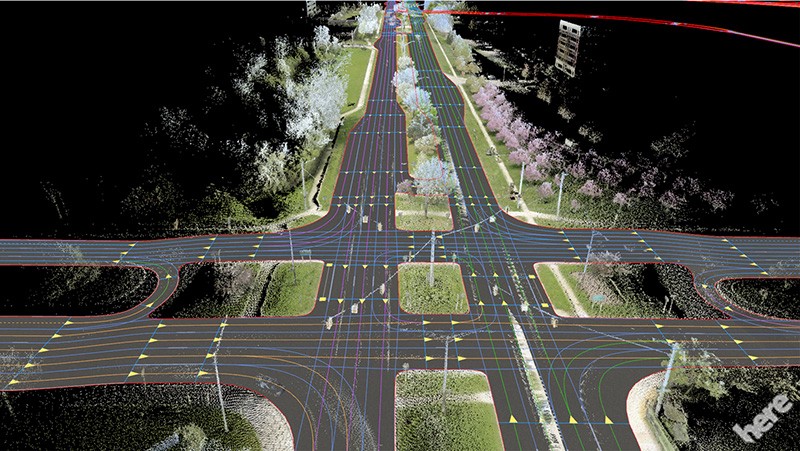
The map — This is our landmarks, roads … There are several types of maps; companies like Here Technologies produce HD Maps, accurate maps centimeter by centimeter. These cards are produced according to the environment where the autonomous car will be able to drive.
Kalman Filters
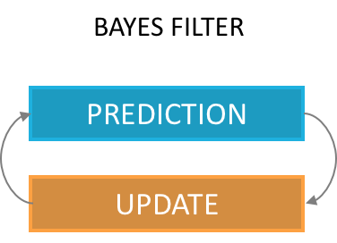
Explained in the previous article, a Kalman filter can estimate the state of a vehicle. As a reminder, this is the implementation of the Bayes Filter, with a prediction phase and an update phase.
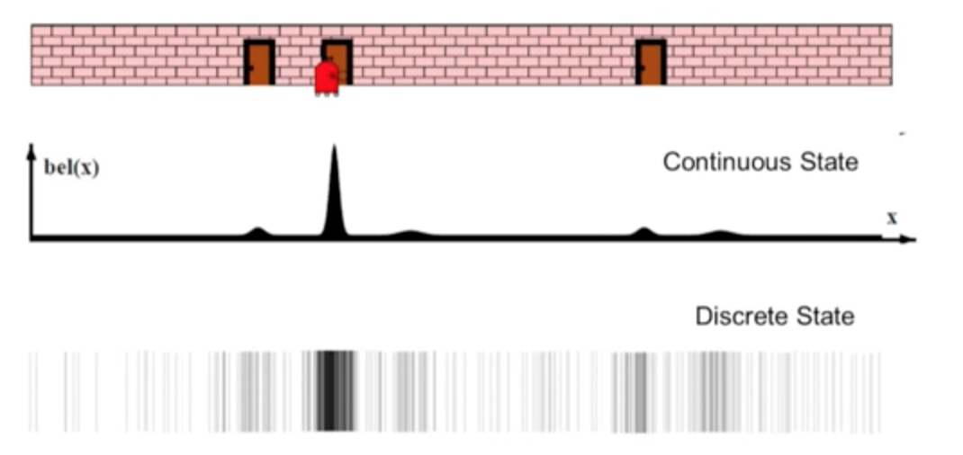
Our first estimate is an equal distribution across the area. We then have a measurement telling us that we are located next to a door. Our distribution then changes to give a higher probability to areas located near doors.
We then perform a motion, our probabilities are shifted with greater uncertainties.
We take a new measurement, telling us that we are next to a door again.
The only possibility is to be located near the middle door.
In this example of a Kalman filter, we were able to locate ourselves using a few measurements and a comparison with the map. It is essential to know the map (including information only the 1st door has an adjacent door) to make deductions. This technique makes it possible not to use an initial position, which is preferable to the technique using odometry.
Particle Filters
A Particle Filter is another implementation of the Bayes Filter.
In a Particle Filter, we create particles throughout the area defined by the GPS and we assign a weight to each particle.
The weight of a particle represents the probability that our vehicle is at the location of the particle.
Unlike the Kalman filter, we have our probabilities are not continuous values but discrete values, we talk about weights.
The implementation of the algorithm is according to the following scheme. We distinguish four stages (Initialization, Prediction, Update, Sampling) realized with the help of several data (GPS, IMU, speeds, measurements of the landmarks).
Localization algorithm
Initialization — We use an initial estimate from the GPS and add noise (due to sensor inaccuracy) to initialize a chosen number of particles. Each particle has a position (x, y) and an orientation θ. This gives us a particle distribution throughout the GPS area with equal weights.
Prediction — Once our particles are initialized, we make a first prediction taking into account our speed and our rotations. In every prediction, our movements will be taken into account. We use equations describing x, y, θ (orientation) to describe the motion of a vehicle.
Motion equations
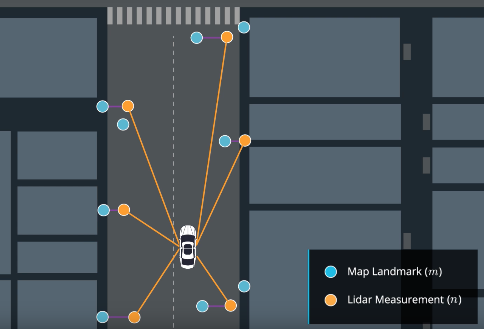
Update — In our update phase, we first realize a match between our measurements n and the map m.
Match between measurements and map
We use sensor fusion data to determine surrounding objects and then update our weights with the following equation :
Update
In this equation, for each particle: – σx and σy are our uncertainties – x and y are the observations of the landmarks – μx and μy are the ground truth coordinates of the landmarks coming from the map.
In the case where the error is strong, the exponential term is 0, the weight of our particle is 0 as well. In the case where it is very low, the weight of the particle is 1 standardized by the term 2π.σx.σy.
Resampling — Finally, we have one last stage where we select the particles with the highest weights and destroy the least likely ones. The higher the weight, the more likely the particle is to survive.
The cycle is then repeated with the most probable particles, we take into account our displacements since the last computation and realize a prediction then a correction according to our observations.
Particle filter in action
Particle filters are effective and can locate a vehicle very precisely. For each particle, we compare the measurements made by the particle with the measurements made by the vehicle and calculate a probability or weight. This calculation can makes the filter slow if we have a lot of particles. It also requires having the map of the environment where we drive permanently.
Results
My projects with Udacity taught me how to implement a Particle Filter in C ++. As in the algorithm described earlier, we implement localization by defining 100 particles and assigning a weight to each particle through measurements made by our sensors.
In the following video, we can see :
A green laser representing the measurements from the vehicle.
A blue laser representing the measurements from the nearest particle (blue circle).
A particle locating the vehicle (blue circle).
The black circles are our landmarks (traffic lights, signs, bushes, …) coming from the map.
Another very popular method is called SLAM, this technique makes it possible to estimate the map (the coordinates of the landmarks) in addition to estimating the coordinates of our vehicle.
To work, we can with the Lidar find walls, sidewalks and thus build a map. SLAM’s algorithms need to know how to recognize landmarks, then position them and add elements to the map.
Localization is an essential topic for any robot or autonomous vehicle. If we can locate our vehicle very precisely, we can drive independently. This subject is constantly evolving, the sensors are becoming more and more accurate and the algorithms are more and more efficient.
SLAM techniques are very popular for outdoor and indoor navigation where GPS are not very effective. Cartography also has a very important role because without a map, we cannot know where we are. Today, research is exploring localization using deep learning algorithms and cameras.
YOLO hẳn đã rất quen thuộc với các bạn trẻ, chúng ta đã nghe từ này biết bao nhiêu lần, khi mà thằng bạn của bạn muốn đua xe đập đá mà bạn ngăn cản, nó sẽ lôi từ này để bật lại bạn, rằng mày chỉ sống có 1 lần thôi, yolo đi.
Câu đó thật ra cũng đúng trong hoàn cảnh bạn biết mình làm gì:)), và trong bài viết này mình cũng nói về YOLO, nhưng không phải về cụm từ kia, mà là một thành tựu lớn của neural network và Image Processing- YOLO( You Only Look One). Nghĩa là chỉ nhìn một lần thôi, lần đầu nghe câu này mình thấy buồn cười, thì hiển nhiên là nhìn một lần chứ mấy lần, còn thấy người đẹp muốn nhìn lại mấy lần thì nhìn chứ, ai cấm:)). Nhưng thật ra câu nói này không phải cho con người, mà là cho computer. Nếu bạn nào đã có kiến thức về Image Processing thì mời lướt qua, còn chưa thì mình diễn tả nôm na như sau: Máy tính nhìn một bức ảnh dưới dạng một ma trận số, và để thực hiện một số tính năng chỉnh sửa ảnh, đầu tiên ta phải xét đến một filter matrix hoặc còn gọi là convolution, convolution matrix này sẽ được nhân với một ô nhỏ trên cùng bên trái của tấm ảnh, sau đó ô này sẽ trượt theo chiều ngang và sau đó xuống dòng đến khi đi hết tấm ảnh. Do đó có thể nói máy tính nó không nhìn tấm ảnh một lần như chúng ta mà nó nhìn từ trái qua phải từ trên xuống dưới. Tất nhiên nhìn kĩ là tốt nhưng làm vậy rất tốn thời gian, trong khi chúng ta chỉ cần nhỉn tổng thể bức hình là có thể chỉ ra trong đó có gì, thì computer cần phải rà hàng trăm hàng ngàn tấm ảnh nhỏ mới làm được điều tương tự. YOLO ra đời để cho phép máy tính làm điều tương tự nhưng tốc độ được cải thiện đáng kể, chỉ quét một lần và nhận diện objects, cho đó nâng cao tốc độ xử lý ảnh lên đến 60 frames/s nhờ đó có thể đáp ứng nhu cầu real-time.
Dưới đây là một số chia sẻ của chính tác giả YOLO:
You only look once (YOLO) is a state-of-the-art, real-time object detection system. On a Pascal Titan X it processes images at 30 FPS and has a mAP of 57.9% on COCO test-dev.
Prior detection systems repurpose classifiers or localizers to perform detection. They apply the model to an image at multiple locations and scales. High scoring regions of the image are considered detections.
We use a totally different approach. We apply a single neural network to the full image. This network divides the image into regions and predicts bounding boxes and probabilities for each region. These bounding boxes are weighted by the predicted probabilities.
Comparison other detector
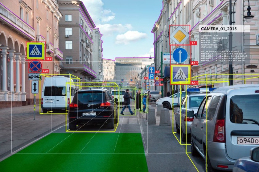
Về cách hoạt động của YOLO mình đã nói ở trên, còn hình bên dưới chính là kết quả hoành tráng mà nó tạo ra. Trong hình bạn có thể thất từng chiếc xe được theo dấu với những hộp bao quanh, và xác định nó là xe lên tới 99%. Không những vậy, đoạn code còn kết hợp với segmentation để nhận dạng đường biên của mỗi chiếc xe, giúp nhận diện chính xác hơn.
Nếu các bạn có hứng thú với đoạn code trong video bên trên, bạn có thể lấy code qua Github của mình, đoạn code được viết bằng Python và sử dụng tensorflow model.
Mình sẽ viết đoạn này bằng tiếng Anh, tiếng việt các bạn có thể dùng tính năng translate nằm bên phải để dịch tiếng việt nhé. Hoặc mình sẽ dịch tiếng việt bên dưới
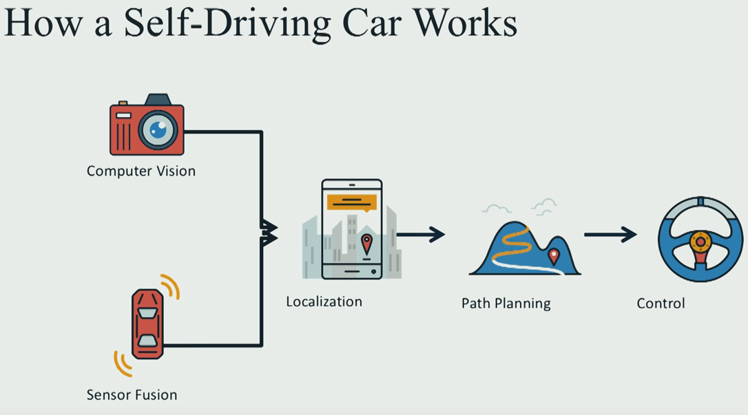
Most of self-driving car on the world work as follow:
Cách mà một chiếc xe tự lái hoạt động được cấu trúc như biểu đồ phía dưới:
Computer Vision(Kỹ thuật xử lý ảnh) + Sensor Fusion(kết hợp sensor: các bạn tạm hiểu là cách hợp các tín hiệu cảm biến lại để đưa ra thông tin chính xác nhất) để đưa ra vị trí chính xác của xe nằm ở đâu trong map. Từ đó xe dùng các thật toán tìm đường Path Planning để đi tới đích, bước cuối cùng là truyền lệnh cho động cơ xe để yêu cầu chạy tốc độ bao nhiêu bẻ lái như thế nào:
Tổng quát chỉ có vậy, nếu các bạn muốn hiểu chi tiết thì hãy đọc đoạn tiếng anh bên dưới(có thế translate nếu muốn)
I/ Generally
Computer vision is how we use images to figure out what the world around us look like. Sensor fusion is how we in-cooperate data from other sensor like laser, Lidars, radar, to get richer understanding out of environment. Once we’ve build this deep understanding of what the world looks like we use path planning to chart a course through the world to get us to where we would like to go. The final step is how we actually turn the sterring wheel and hit the throttle, and the brake in oder to execute the trajectory that we build during path planning.
II/ Computer Vision
Computer Vision using the camera mounted in front of the car, to detect lane and other vehicle. It looking for color and edges and gradient to find the lane on the road and then train a deep neural network to draw the bounding box around the other vehicle on the road.
Deep neural network and deep learning is exciting new part of machine leaning and artificial intelligent. And this is the way that computer can learn what cars and other object look like by simply sending them lots and lots of data they see lots of cars and this is pretty similar to what advance driving assistance system do on the road today.
II/ Sensor Fusion
Once we know what world look like by images, the next steps is augment that understanding of the world using other sensor so radar and laser to get measurement that are difficult for the camera alone to understand so things like distance between our car and other car and how fast other object in the environment moving.
A Lidar which has an array of laser doing a 360 degrees scan to to world and seeing the different object in that environment looks like and how they move.
So once we understand both what the world look like and how to measure it and we cooperate those understanding together to get rich picture of our surrounding environment, the next step is to localize ourself in that environment.
III/ Localization
Maybe people think GPS today can localize ourself in cellphone. we absolute now where we are but it not really like that, because GPS uncertainty is about 1 to 2 meter. And in self-driving we need the absolute accuracy, because if a small mistake happen, it very dangerous for your car if you running on the hight way with 150 to 200km/h. So we have to use much sophisticated mathematical algorithm as well as hight definition map to localize our vehicle precisely in it environment to single digits centimeter level accuracy.
Using particle filter is very good way to localize a vehicle in an know environment. Measuring distance from various landmarks ans it’s figuring how far is it from these landmark and where it see the landmark and comparing that to the map and using that to figure out precisely where it is in the world , those landmark might be things like streetlight, or traffic sign, mail boxes or even manhole covers.
IV/ Path Planning
When we know how the world look like and where were are in this world, the next step is to actually chart a path plan through that world to figure out how to get where we want to go, and this is path planning. This program cerate a path planner which predict where the other vehicles on the road are going to and then figures out the maneuver our vehicle should take in response and finally build and series of way points those are the green points in the video for the car driver through that’s the trajectory the car should follow and you see if the vehicle comes up on other traffic it has to figure out should it slow down and stay in it lane or should it shift right or should shift left. And this is the type of decision that real self-driving car had to make all the time subject to constraints like speed limit and acceleration limit.
V/ Control
Final step in the pipeline is control. Control is how we actually turn the steering wheel and hit the throttle and hit the brake in oder to execute that trajectory that we build during path planning.
If you want to go in detail, you can apply to Udacity self-driving car program, there you will be learn theories, programming skill with the best professors and the best engineers form over the world
Vision-based Navigation là một trong những lý thuyết về công nghệ tự hành (autonomous driving). Bên cạnh Laser-Base, IMU-base, thì vision base là một công nghệ có thể nói là khá rẻ, chỉ cần một 3D-camera(stereo-camera hoặc Kinect), ta có thể chụp được hình ảnh 3D của môi Trường xung quanh dùng vision odometry để xác định vị trí và hướng đi của robot trong map và có thể nói là chúng ta đã thực hiện xong SLAM(Simultaneous Localization and Mapping).
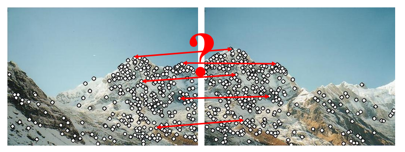
Để nói về vision-base trước tiên cần nói về cách để chúng ta match hai tấm ảnh lại. Khi ta sử dụng camera để chụp ảnh thì chỉ chụp được một tấm vào một thời điểm thôi. Nhưng khi bạn dung panorama chẳng hạn, thì có thể chụp được tấm hình với góc rộng hơn nhiều chi tiết hơn sẽ được thể hiện. Chế độ panorama có thể làm được điều này nhờ ghép các tấm ảnh đơn lẻ lại với nhau. Nhưng ghép như thế nào, hôm nay chúng ta sẽ tìm hiểu về điều đó.
Nhìn vào hai tấm ảnh trên ta thấy chúng được chụp ở 2 góc gần nhau, tấm thứ hai dịch qua phải một tí. Và nếu mình muốn thấy hết dãy núi thì phải ghép hai tấm lại. Và các bước ghép như sau:
1/ Đầu tiên ta sẽ nhìn ra những điểm quan trọng trong một bức hình, gọi là features detection, bởi vì bức hình là một tập hợp những điểm ảnh, và chỉ cần một số điểm ảnh là có thể miêu tả gần như đầy đủ tấm hình. Có nhiều cách để tách các features từ tấm ảnh, ví dụ như ta dùng Canny edges detection. Hoặc là dùng convolution high pass filter quét qua tấm ảnh để thu được những khu vực có độ tương phản cao (high contrast). Sau khi làm các bước trên ta có tấm hình như sau.
2/ Sau khi xác định được các điểm quan trọng, việc tiếp theo là nối tụi nó lại, vấn đề là nối thế nào?
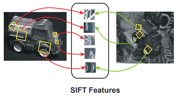
Trước tiên ta phải nhận dạng các features mà ta detect được, bởi muốn ghép hai tấm hình ngọn núi lại, vậy thì khu vực nào phải ghép với khu vực đó, như chân núi ghép với chân núi, đỉnh núi ghép với đỉnh núi. Không thể lấy râu ông nọ cắm cằm bà kia được. Các features được chọn phải đặc biệt, và vẫn giữ đặc tính khi bị xoay hoặc di chuyển.
Một trong những Phương pháp áp dụng là SIFT(Scale invariance features transformation):
Ý tưởng của SIFT:
Nội dung của một bức ảnh sẽ được lấy ra để vào một khu vực, ở đây ta gọi là “túi ảnh”. Túi này chứa những features nói lên đặc tính của tấm ảnh thứ nhất. Khi so sánh với tấm ảnh thứ hai được chụp từ một góc khác , những features được so sánh để xác nhận xem hai tấm có giống nhau hay không.
Xin chào các bạn, trong block này mình sẽ hướng dẫn các bạn cách sử dụng phần mềm DOORS của IBM.
IBM Rational Doors: Getting Started
Đầu tiên phải đăng nhập vào chương trình
Ở trang làm việc, những thứ cần chú ý gồm có hình trụ ở góc trái của màn hình làm việc(work space), ở đó là Database Root, tiếp đến là Folder, và rồi bên trong folder là Project, thanh bar phía trên hiển thị location of current selection. Hình phía dưới hiển thị Default Workbench của DOORS.
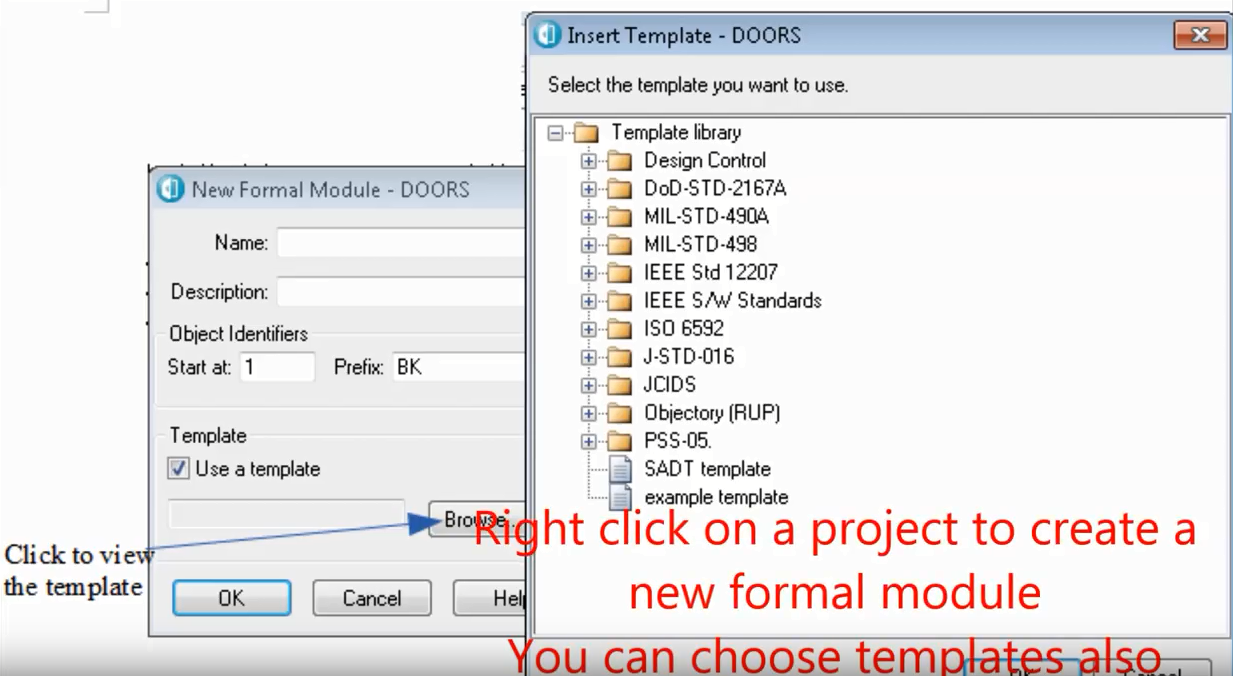
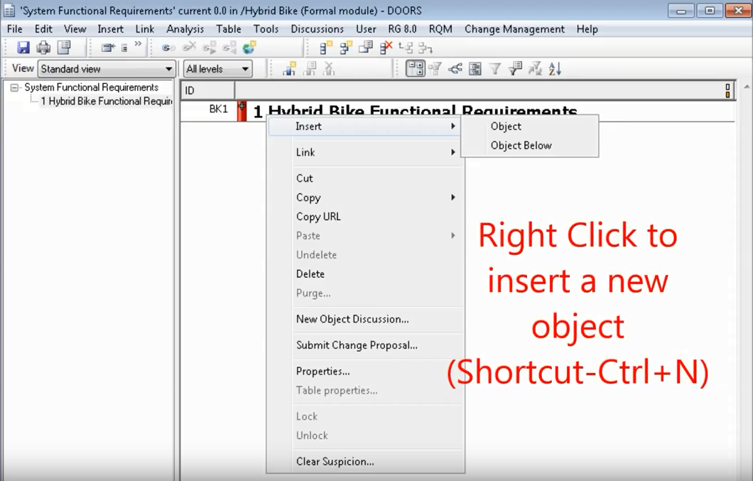
Click chuột phải vào icon project để tạo ra một formal module mới, bạn cũng có thể chọn template ở đây bằng cách click chuột trái vào browse icon.
Sau khi các bạn tạo ra formal module cho riêng mình, chuột phải vào module đó để tạo ra một object mới. Các bạn cũng có thể dùng phím tắt để làm điều tương tự.
Hình phía dưới giải thích những vị trí của objects, gồm có level1 object, level2 objects là con của level1 object. Ở bên trái là ID của objects.
Click chuột phải vào level2 object sau đó click vào properties để thêm text vào object.
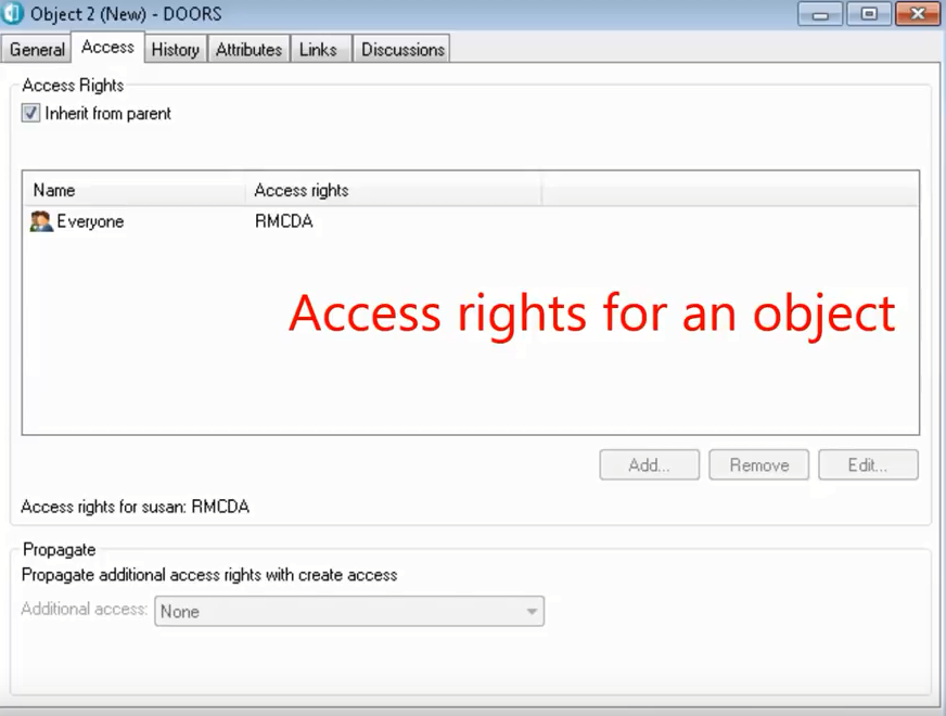
Đây là access của một object, bạn có thể chọn bằng cách bấm qua chọn access bên cạnh general.
Bạn cũng có thể thêm table từ table menu dưới mỗi object, khi add table bạn có thể set hàng và cột. Sau khi add table xong thì sẽ như hình sau.
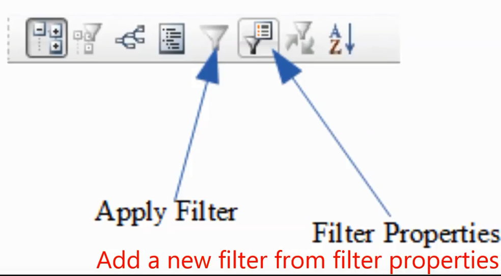
Chúng ta có thể thêm filter bằng cách click chuột vào biểu tượng filter properties.
Thêm một object mới bằng cách click chuột phải vào một object chọn Link, start Link. Sau đó click một cái object Link mới, chọn link from start để hoàn thành quá trình link.
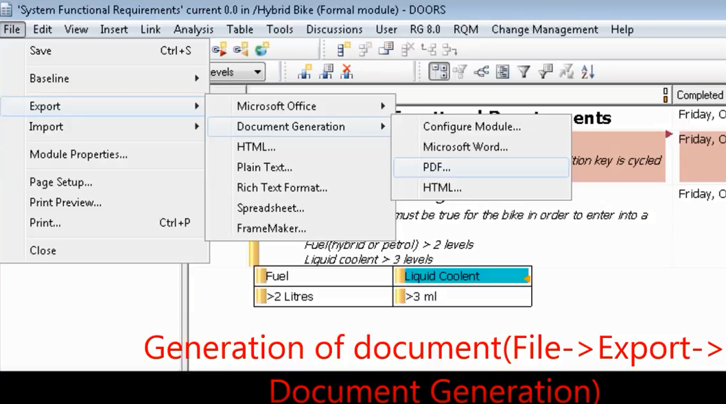
Để tạo ra một document, chọn File -> Export -> Document Generation như hình bên dưới.
Occupancy-grid maps (H.P. Moravec, 1988; H.P. Moravec et al, 1989; A. Elfes, 1987, A. Elfes, 1989; S. Thrun et al, 2005) :
Occupanny-grid map (bản đồ lưới) thể hiện môi trường được chia nhỏ thành các mắt lưới, các ô này có thể tự do( free) hoặc bị chiếm giữ( occupied), mỗi ô đại diện cho một diện tích thực tế trong môi trường thực và mỗi ô sẽ có một giá trị biểu diễn xác xuất nó có đang bị chiếm giữ hoặc tự do (chiếm giữ ở đây nghĩa là ở đó có vật cản, hoặc tường .., tự do(free) nghĩa là tại vị trí đó không có gì cả, và chúng ta có thể đi qua khu vực đó.
Giá trị occupancy của ô thứ nhất trong occupancy grid-map tại thời điểm t được biểu diễn bởi xác xuất p, .. P tại thời điểm t phải nằm trong khoảng từ 0 tới 1. Ta có thể hiểu rằng P= 1 nghĩa là ô đó bị chiếm giữ(occupied), P=0 nghĩa là ô đó trống(free), P=0.5 nghĩa là không biết(unknown) hoặc khu vực chưa khám phá (unexplored area).
Các bạn có đồng ý rằng, Robot không có bất kì nhận định nào về thế giới mà lần đầu nó bị đặt vào trong đó. Cũng như bạn bị bắt cóc đến một nơi xa lạ vậy, bạn hoàn toàn mất phương hướng. Do đó P sẽ có giá trị P=0.5 co tất cả i tại thời điểm t=0. Map sẽ được cập nhật thông qua log odds của occupancy. Sự vượt trội của log odd là nó có thể tránh được sự nhập nhằng giữa 0 và 1, vì đôi khi giá trị của nó sẽ là 0,3 hoặc 0,7. Do đó, ta có cách tính tình trạng bị chiếm giữ của ô thứ n trong grid-map theo công thức sau:
với lt-1 là log odds được tính từ giá trị occupancy của ô tại thời điểm t-1. Hình 1(a) miêu tả quá trình cập nhật của map. Ô màu đen thể hiện tia laser gặp phải vật cản ở đó ngược lại các ô màu trắng thể hiện là những vị trí có tia laser đi qua nhưng không bị cản trở, ô màu xám là nơi tia laser không đi qua. Hình 1(b) thể hiện trường hợp tia laser không gặp vật cản nào nhưng đạt mức maximum của nó.
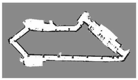
Hình ảnh dưới đây là Occupancy Grid map trong thực tế được tạo bởi một máy quét laser, khu vực rìa màu đen thể hiện vật cản, khu vực trắng là trống và khu vực màu xám là tia laser chưa đi qua.
Topological Maps,
Không giống như occupancy grid map, topological maps (D. Kortenkamp et al, 1994; H. Choset, 1996; H. Choset et al, 1996) không thể hiện môi trường xung quanh một cách trực quan bằng cách chia nhỏ bản đồ ra như trên. Thay vào đó, topological map thể hiện môi trường quanh nó như một đồ thị (graph).
Giống như trong hình 3. Một danh sách những khu vực quan trọng như tường, góc, cửa hoặc hành lang, những khu vực này được thể hiện dưới dạng các điểm(node) m. Sự liên kết giữa các điểm m được thể hiện dưới các liên kết Uk. Trong rất nhiều topological map, khoảng cách giữa các khu vực cũng được thể hiện trong các sợi dây liên kết các nodes này. Sự ưu việt của topological map là nó thể hiện các khu vực trong map rất chi tiết, ta có thể zoom vào để xem đặc tính từng khu vực, điều này lý giải tại sao topological map được dùng để phát triển 3D-map.
Topological maps là sự lựa chọn tối ưu hơn nếu người dùng quan tâm dung lượng bộ nhớ. Trong trường hợp chúng ta sử dụng laptop hay raspberry pi có dung lượng bộ nhớ thấp. Đó là bởi vì ít memory cần để lưu giữ nodes so với một số lượng lớn các ô được sử dụng trong grid-map. Tuy nhiên điều này cũng đồng nghĩa với, graph-map sẽ ít chính xác hơn grid-map. Lý do là một số thông tin quan trọng ví dụ như vị trí của các ô màu xám mà tia laser không đến được sẽ không được hiển thị trong bản đồ. Do đó khi robot sử dụng graph-map sẽ không thể di chuyển nhanh mà vẫn giữ an toàn như sử dụng grid-map, lời khuyên là khi sử dụng topological map thì nên cho robot di chuyển chậm thôi.
Trong bài viết này mình sẽ nói về một đề tài rất thú vị, đó là “Xe tự lái “, hẳn các bạn cũng nghe về chủ đề này nhiều rồi. Đây là một hướng đi mới cho ngành công nghiệp xe hơi vốn ít có những thay đổi đột phá từ khi những chiếc xe bốn bánh lần đầu tiên lăn bánh trên đường vào đầu thế kỉ 19, đến nay đã gần 200 năm trôi qua và chúng vẫn là … xe bốn bánh:)).
Mặc dù có rất nhiều nâng cấp về tốc độ, mẫu mã, nhiên liệu sử dụng, nhưng khi nói về auto quan niệm của chúng ta vẫn là một cỗ máy 4 bánh được mấy bác tài xế lái đưa chúng ta đi mọi miền tổ quốc. Vâng, người lái ở đây chính là điểm mấu chốt, chứ không có ai lái thì xe xịn mấy cũng đắp chiếu!
Vào năm 2004 đã có 1 cuộc thi về những chiếc xe có thể tự vận hành mà không cần người điểu khiển đã được tổ chức tại Mỹ, từ đây đã tạo ra một cuộc chạy đua giữa các công ty ô tô, để sản xuất chiếc xe tự lái cho riêng mình. Hẳn các bạn thắc mắc là tại sao từ năm 2004 đến nay đã là 2018, nhưng vẫn chưa thấy xe tự lái xuất hiện. Thực ra là nó đã xuất hiện và đang được các công ty chạy thử nghiệm rồi, chỉ là đang hoàn thiện nên bản thương mại hóa chưa được bán.
OK, mình nghĩ nói về lịch sử như vậy là đủ, bây giờ mình sẽ nói về cách thức hoạt động của một chiếc xe tự lái:
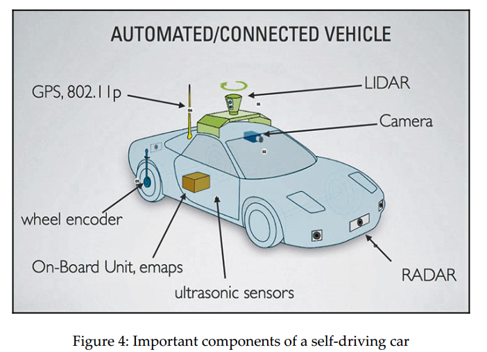
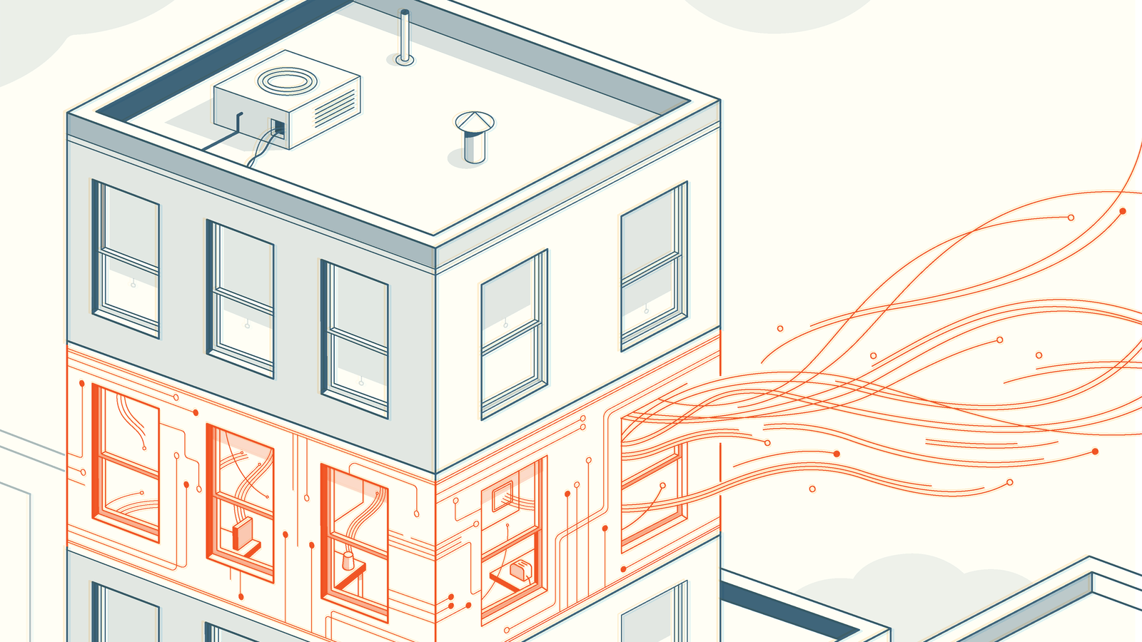
Hình trên mô tả các bộ phận của một chiếc xe tự lái, bao gồm:
LIDAR, máy quét laser dùng để quét môi trường xung quanh và tạo ra một bản đồ khu vực(local map) xung quanh xe.
Camera, được gắn trước mũi xe để tính toán xem xe có chạy đúng làn hay không, nó cũng được tích hợp một số thuật toán xử lý ảnh kết hợp với machine learning để phân biệt được những biển báo giao thông và các phương tiện giao thông khác.
Một Radar được gắn trước mũi xe, để xác định khoảng cách tới xe phía trước, từ đó đưa ra vận tốc chạy xe hợp lý.
Ultrasonic sensor được gắn ở cửa bên hông xe, để tính khoảng cách với lề đường hoặc các xe chạy bên cạnh.
On-board unit chính là bộ xử lý chính của xe tự lái, thường sẽ là một bộ vi xử lý mạnh như là Intel Xenon và GPU để tổng hợp dữ liệu từ các cảm biến nói trên. E-map chính là bản đồ khu vực được máy chủ của xe kết hợp với GPS để biết chính xác vị trí của xe.
Wheel encoder, chính là cái bánh, nói đúng hơn thì là bộ phận trực tiếp điều khiển bánh xe, nó sẽ nhận lệnh từ on-board unit như là rẽ phải, quẹo trái, đi thẳng.., và điều khiển bánh xe theo những lệnh này.
Như các bạn đã biết, GPS là dùng để định vị chúng ta trên thế giới này với sự giúp đỡ của vệ tinh, và chúng ta cũng biết là nó không chính xác lắm, tầm 99% thôi. GPS được dùng để xác định Kinh độ và Vĩ độ của chiếc xe. Sự chính xác của GPS được cải thiện bởi các loại cảm biến được gắn trên xe, một số cảm biến có độ chính xác được tính bằng m, một số chính xác nhỏ hơn 1 mét. Bng cách kết hợp GPS, IMU (Inertial measurement units) và wheel odometry data, bằng thuật toán sensor fusion, vịtrí của xe được xác định một cách chính xác hơn.
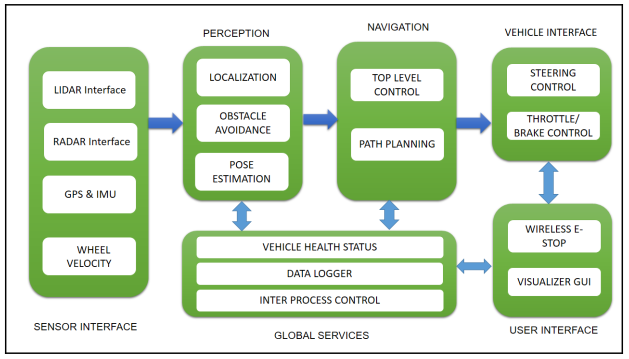
Dưới đây là block diagram (sơ đồ hoạt động) của một chiếc xe tự lái được sử dụng trong DARPA Challenge:
Sensor interface modules: Bao gồm tất cả tương tác giữa các cảm biến và chiếc xe ,những cảm biến chính của xe bao gồm LIDAR, Radar, camera, IMU, GPS và wheel encoders.
Perception modules: Đây là nơi tiếp nhận và xử lý tín hiệu từ tất cả các cảm biến như LIDAR, camera… để định vị những vật thể tĩnh hoặc động ở môi trường xung quanh xe và tạo ra một bản đồ cục bộ, đồng thời cũng giúp xác định vị trí của chính chiếc xe dựa trên vị trí của các vật trong bản đồ cục bộ nói trên.
Navigation modules: Xác định hành vi của chiếc xe tự lái, bao gồm tính toán quãng đường đi chính xác nhất cho xe cũng như điều khiển các module khác như là thắng khẩn cấp hoặc gạt nước tự động.
Vehicle interface: Sau khi tính toán được quãng đường ngắn nhất, các lệnh điều khiển, bao gồm điều khiển vô-lăng, bánh xe, thắng, sẽ được gửi từ bộ vi xử lý tới chiếc xe thông qua Drive-By-Wire(DBW) interface. DBW về cơ bản được xây dựng giống như CAN Bus system.
User interface: Đây là nơi chúng ta có thể thấy và tương tác được với hệ thống xe tự lái, bao gồm màn hình touch screen để chúng ta có thể nhập điểm đến, hoặc có thể điều khiển bằng giọng nói. Tất nhiên cũng có nút bấm để ngắt toàn bộ hệ thống trong trường hợp nguy hiểm.


